LiFi Optical Audio Link
Sigma-Delta transmitter and a four-stage analog optical receiver, laid out, etched and soldered by hand, then validated stage by stage on the oscilloscope.
THE STORY
A Licence 3 EEA project at Université Paris-Saclay: send audio over light. The transmitter encodes the audio as the duty cycle of a self-oscillating first-order Sigma-Delta loop and switches an LED fully on or off. The receiver has to pull that ~97 kHz signal out of a photodiode current dominated by room light. The circuit topologies were given by the instructor; my part was the receiver: the analysis, the EAGLE schematic and two-layer layout, etching, drilling, soldering, debugging, and measuring every stage.
MY CONTRIBUTIONS
- Analysed the transimpedance front end (BPW34, Rf = 22 kΩ, Cf = 10 pF) and checked the compensation capacitor against the op-amp gain-bandwidth.
- Captured the receiver in EAGLE, chose footprints, placed and routed a two-layer board, and ran the DRC before fabrication.
- Fabricated the board myself (UV exposure, ferric-chloride etch, drilling, soldering), then fixed shorts, cold joints and placement errors.
- Validated each stage with the oscilloscope: TIA, conditioning (LM318), hysteresis comparator (LM311) and reconstruction filter (LF356).
- With the team, measured the Sigma-Delta transmitter and checked its duty cycle against the charge-balance law.
Solution highlights
A complete optical audio link: the information rides on the timing of the light pulses, not their brightness, so the receiver only has to decide "on or off" and average the answers.
- Transmitter: LF356 integrator + LM311N quantizer forming a first-order Sigma-Delta loop.
- Receiver: photodiode TIA (LM318) → LM318 conditioning → LM311 hysteresis comparator → LF356 Sallen-Key low-pass.
- Full English report with equations, bench data, LTspice results and an honest limits section.
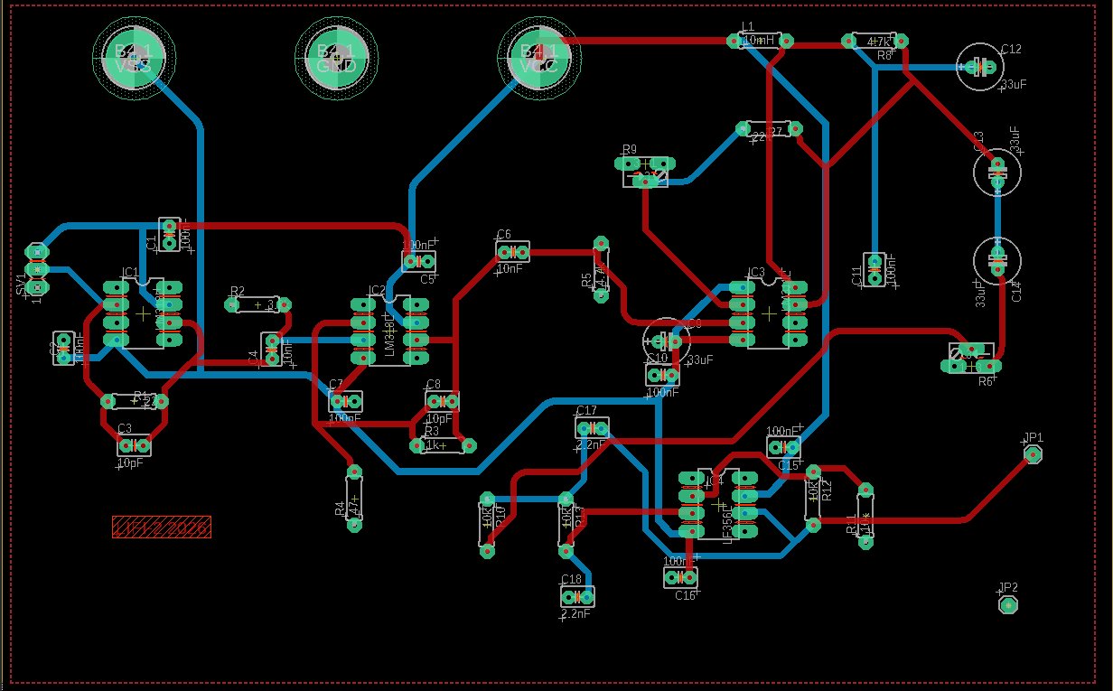
EAGLE two-layer layout of the receiver
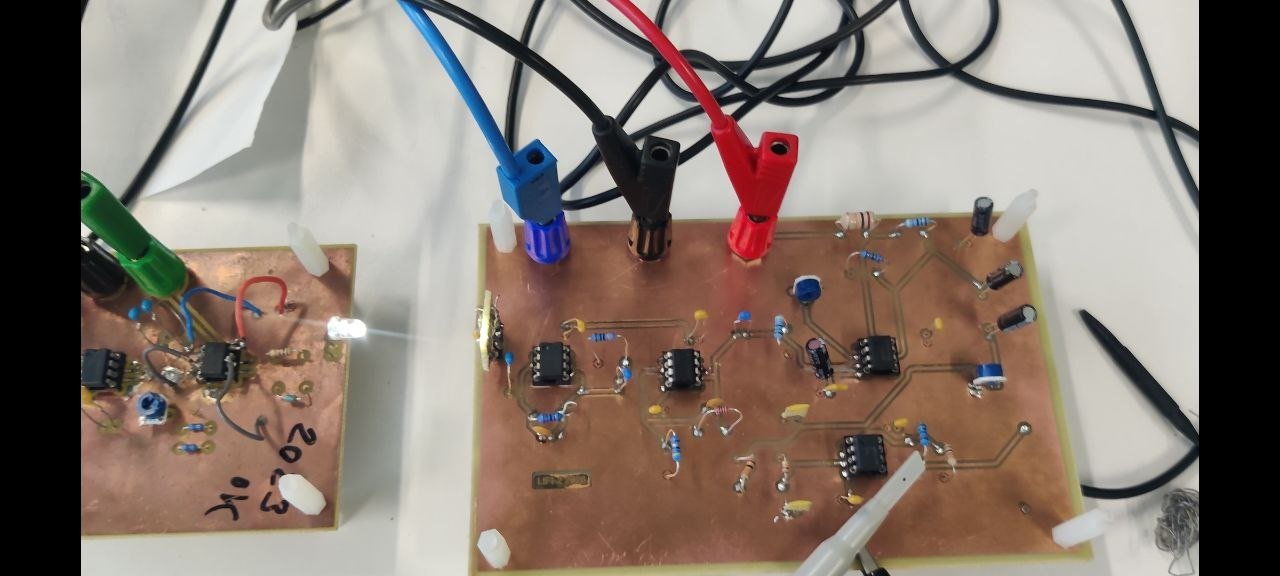
The fabricated board under test
The problem
A photodiode cannot tell an LED photon from a ceiling-light photon. The wanted signal is a small current at ~97 kHz sitting on a large DC and 50/100 Hz current from ambient light, and a larger feedback resistor amplifies both.
The insight
Separate signal from interference by frequency, not amplitude. Ambient light lives near DC, audio below 20 kHz, switching near 90 kHz. LTspice showed that a 1500 Hz disturbance ruins a direct analog link but disappears once a comparator regenerates the PWM edges before the filter.
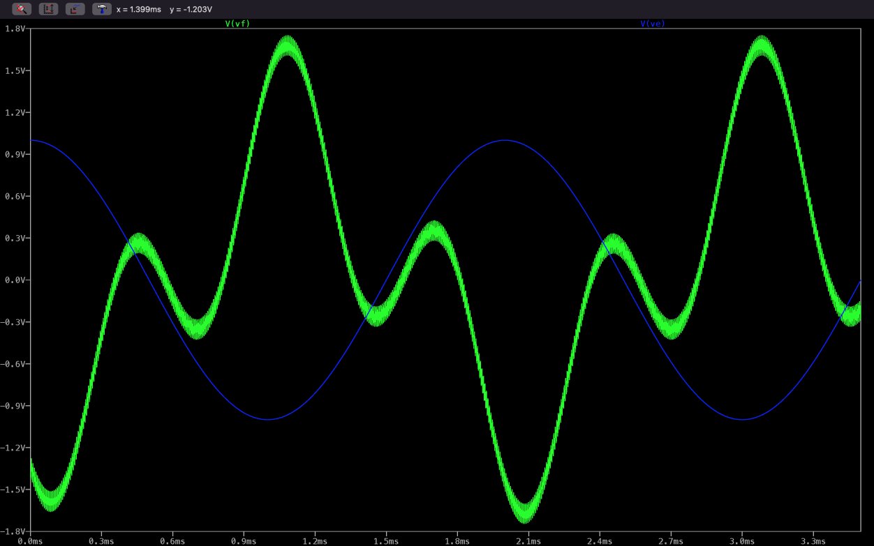
LTspice: 1500 Hz disturbance passes the RC demodulator
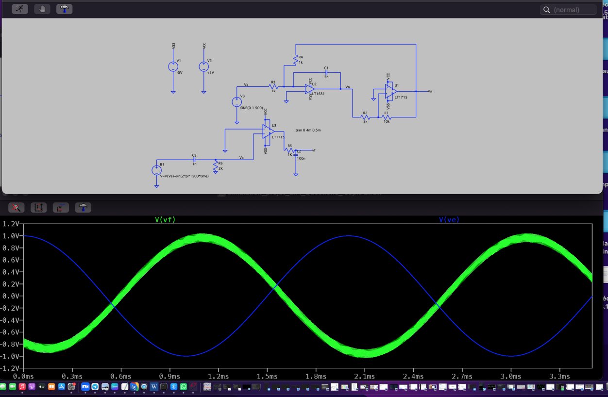
LTspice: comparator regeneration restores the 500 Hz tone
Transmitter measurements
At zero input the loop self-oscillates at 86.82 kHz with a 52.87 % duty cycle. A +1 V input moves it to 41.95 %, shifting the output average by −1.09 V, close to the −R4/R3 ≈ −1 predicted by charge balance. With a 1 kHz sine the edges sweep while the mean switching frequency stays at 86.13 kHz.
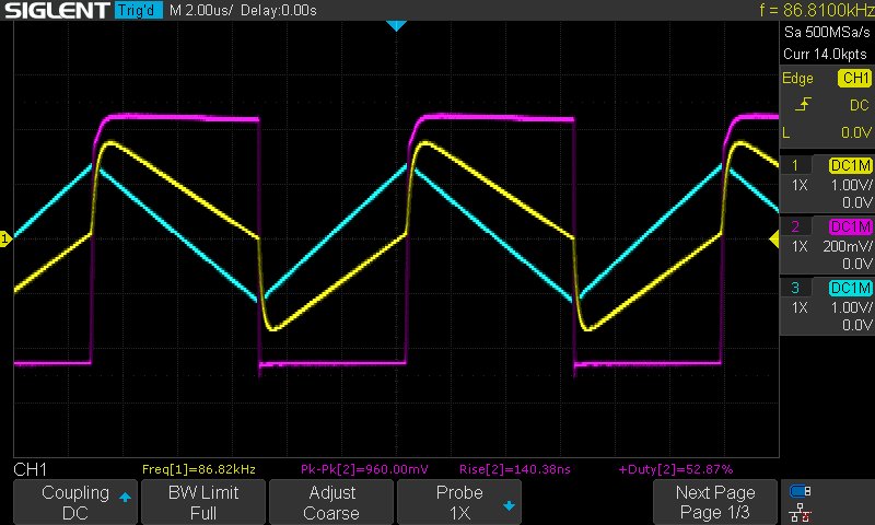
Vin = 0 V: integrator ramps and comparator output
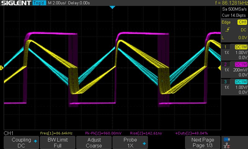
1 kHz sine input: duty cycle follows the audio
Up close: from schematic to board
Short photodiode-to-TIA path, decoupling at every supply pin, wide power and ground tracks, 45° bends, and a DRC pass before export. The artwork was printed, UV-exposed, etched in ferric chloride, drilled and soldered in the lab.
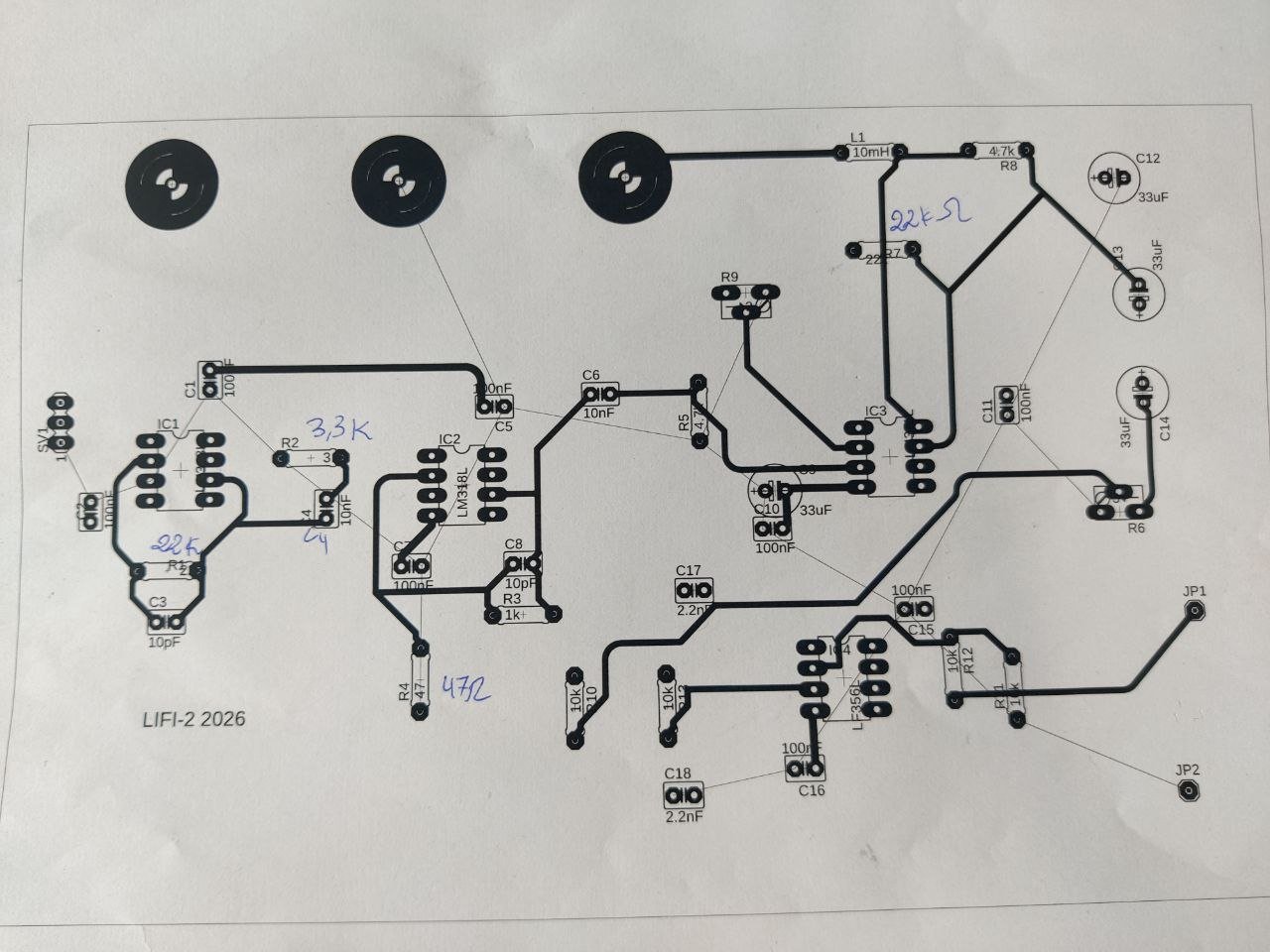
Printed artwork used for UV exposure
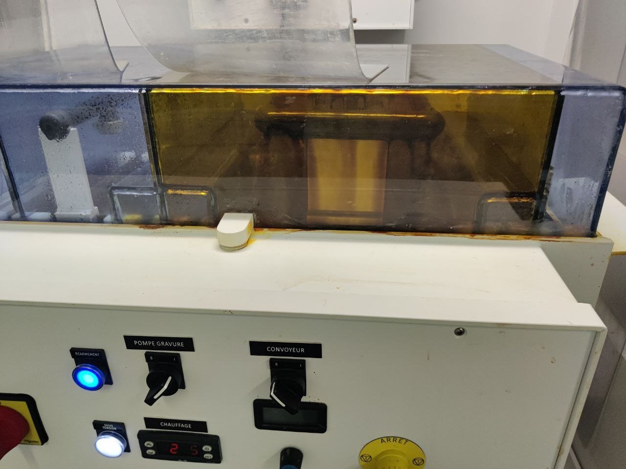
Etching machine used to make the board
Under the hood: TIA stability check
The 72 pF photodiode capacitance at the inverting input erodes phase margin, and Cf across Rf restores it. A first-pass estimate gives about 6 pF for the LM318 used on the final board, so the 10 pF fitted is conservative, and the closed-loop bandwidth 1/(2π·Rf·Cf) ≈ 720 kHz still clears the switching rate.
from math import pi, sqrt
Rf, Cin, Cf = 22e3, 72e-12, 10e-12
for name, gbw in [("LM318", 15e6), ("LF356", 5e6)]:
    print(name, "Cf_min ~", round(sqrt(Cin / (2*pi*Rf*gbw)) * 1e12, 1), "pF")
print("closed-loop BW ~", round(1 / (2*pi*Rf*Cf) / 1e3), "kHz")Receiver validation & what went wrong
Under constant light the TIA sat at about +2 V of ambient offset and the comparator stayed locked at about −4 V, as expected. With the ~97 kHz optical signal the comparator regenerated a clean square wave. The conditioning stage showed overshoot and ringing on rising edges; the comparator hides it, but it points to limited phase margin and is the first thing I would fix.
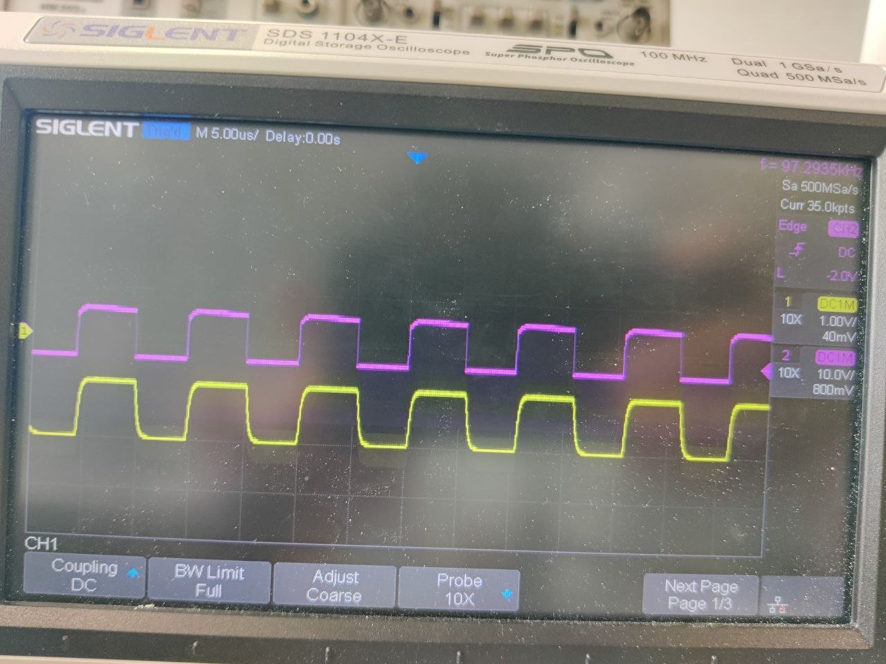
TIA output: ~1 Vpp with rounded edges
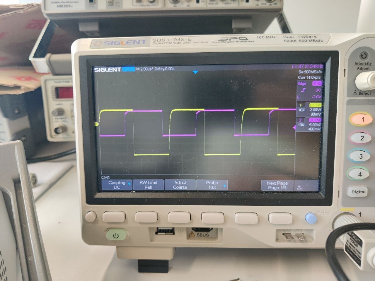
Comparator output: sharp edges, flat plateaus
Limits
The receiver board was validated with a fixed-duty optical signal and the transmitter separately with a 1 kHz sine. A full end-to-end audio test (distortion and SNR versus distance and room light) is the next step.
Reflection / what I learned
Real circuits do not behave like ideal schematics. Ambient-light offset, the TIA phase-margin trade-off and ringing in a fast amplifier only appeared once the board existed, with its parasitics, layout and grounding. Explaining those gaps with an oscilloscope is what pushed me towards research in power electronics and EMC.